
Understanding the Electrical Connection of the Dupline Bus Terminator DT01
Understanding the Electrical Connection of the Dupline Bus Terminator DT01
In modern industrial automation, Carlo Gavazzi’s Dupline system stands out as a robust, flexible, and cost-effective fieldbus solution for decentralized control and signal transmission. Among its many components, the Dupline Bus Terminator DT01 plays a crucial yet often underestimated role — ensuring the stability and reliability of the communication network.
This article explores the electrical connection principles, wiring configuration, and best installation practices for the Dupline DT01 terminator, helping engineers achieve optimal system performance. For more technical details and related components, visit www.carlogavazzidupline.com.
1. The Role of the DT01 Bus Terminator in a Dupline Network
In every Dupline fieldbus network, data and power signals are transmitted along a two-wire bus. These signals are susceptible to reflections and noise if the line is left open-ended. The DT01 Bus Terminator is designed to absorb these reflections and match the line impedance, ensuring stable signal transmission across long distances.
Without proper termination, signal integrity decreases, leading to data errors, delayed communication, or even loss of device synchronization. Installing a DT01 module at the end of each bus segment prevents such interference, maintaining clean and reliable data exchange.
2. Electrical Connection and Wiring Configuration
The electrical connection of the Dupline DT01 is intentionally simple yet must follow best wiring practices to guarantee performance:
Connection Overview
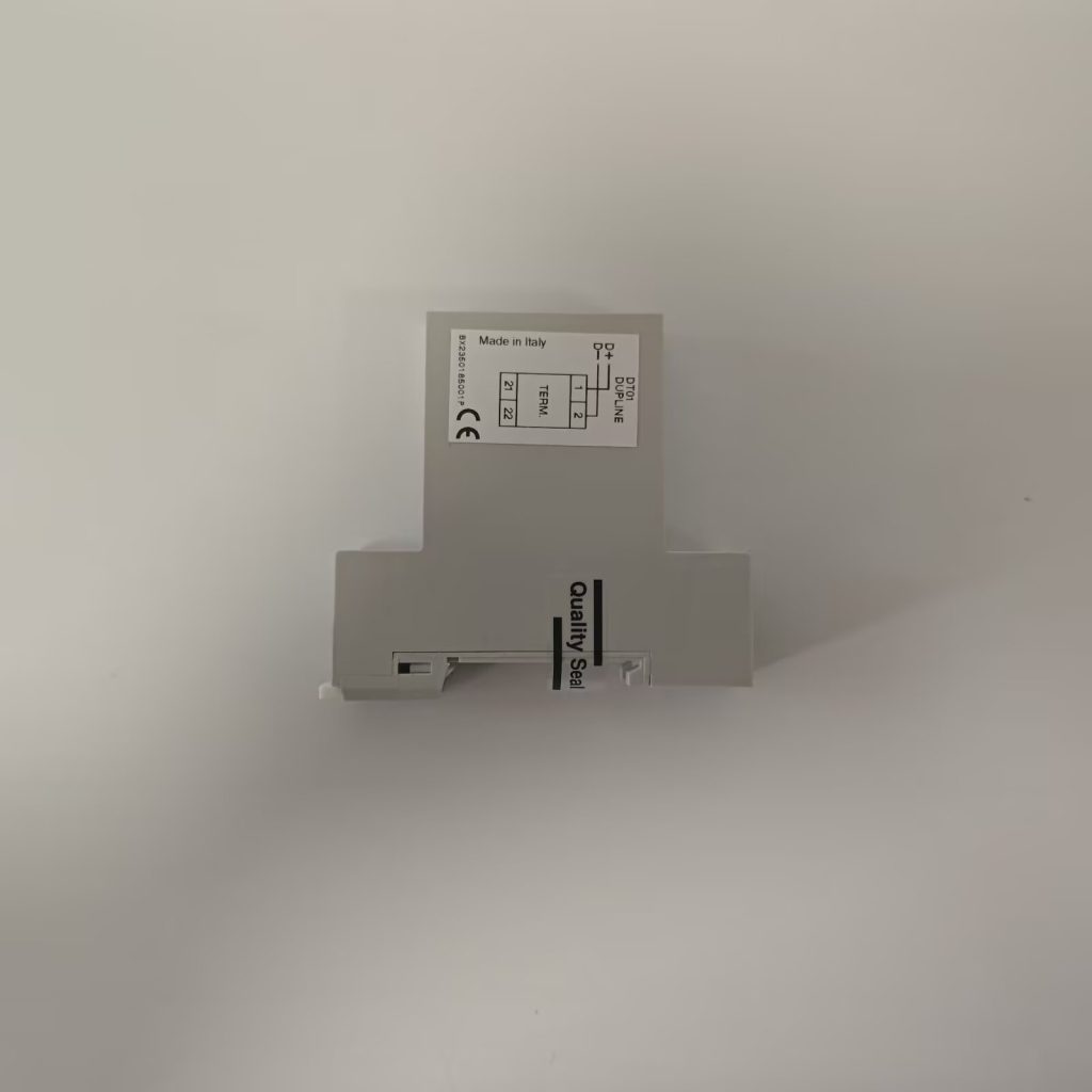
- Bus Terminals: The DT01 connects directly across the two Dupline bus wires (D+ and D–).
- Polarity: The device is non-polarized, which means the two wires can be connected in either direction.
- Voltage: The typical Dupline operating voltage is 8.2 V AC (nominal), generated by the system master or power supply.
- Current Consumption: The DT01 draws a minimal current, typically in the microampere range, ensuring no significant load on the network.
Step-by-Step Wiring Guide
- Locate the end point of the Dupline bus cable, typically at the last field device or junction box.
- Strip approximately 5–7 mm of insulation from both bus wires.
- Connect the two wires to the DT01 screw or spring terminals marked “Dupline Bus.”
- Secure the wiring using appropriate cable glands or protective conduits to prevent mechanical stress.
- Verify network continuity using a Dupline test unit (such as the Carlo Gavazzi GTU8) before powering up.
💡 Pro Tip: When installing multiple network segments or repeaters (for example, using Carlo Gavazzi GS38920000230), each segment must have its own DT01 terminator installed at the farthest end.
3. Electrical Characteristics and Technical Insights
The DT01 terminator is internally built with a resistor-capacitor (RC) network, tuned to match the characteristic impedance of the Dupline cable. This prevents standing waves on the line and provides an electrically damped end point for signal transmission.
| Parameter | Typical Value | Description |
|---|---|---|
| Rated Voltage | 8.2 V AC | Dupline system voltage |
| Connection Type | 2-wire, non-polarized | Simple connection to D+ / D– |
| Mounting | DIN rail or enclosure mounting | Easy integration |
| Power Dissipation | < 10 mW | Negligible heat generation |
| Function | Bus line termination | Ensures signal integrity |
This simplicity in design is what makes DT01 a preferred choice for field engineers: no external power, no programming, just plug and terminate.
4. Best Practices for Reliable Electrical Performance
To fully leverage the Dupline network’s reliability, follow these field-tested guidelines:
- Always terminate both ends of long bus lines to avoid reflection-induced noise.
- Use shielded twisted pair cables for extended runs in high-EMI environments.
- Avoid star topologies — Dupline performs best in daisy-chain configurations.
- Check for loose connections periodically; even minor oxidation can affect impedance balance.
- Combine DT01 with surge protection modules in outdoor or industrial sites for enhanced system robustness.
5. Integration with Other Dupline Components
The DT01 seamlessly integrates with the complete Dupline ecosystem, including:
- Dupline gateways (e.g., SD2DUG24) for interfacing with higher-level control systems.
- Input/Output modules (e.g., G50102206) for signal acquisition and control.
- Field repeaters (GS38920000230) for extending communication range.
- Configuration and diagnostic tools (GAP1605, GTU8) for commissioning and testing.
When properly connected, the DT01 ensures the network’s electrical equilibrium, allowing all Dupline modules to communicate reliably over distances up to several kilometers.
6. Conclusion
The Carlo Gavazzi Dupline DT01 Bus Terminator may appear to be a simple passive component, but it plays a critical electrical role in ensuring the entire fieldbus operates at peak stability. Proper wiring and termination are fundamental to the success of any Dupline installation.
For engineers, integrators, and automation specialists seeking detailed installation manuals, wiring diagrams, and compatible accessories, visit www.carlogavazzidupline.com — your trusted resource for Dupline fieldbus technology.